Diagram reading order
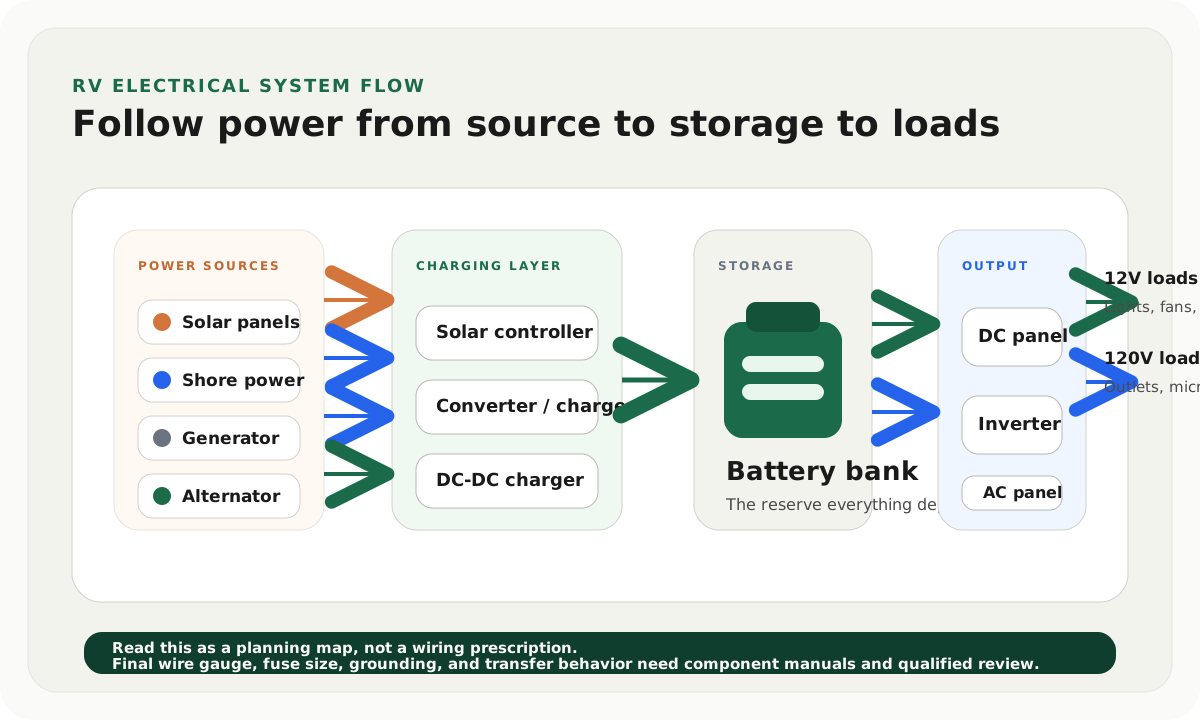
Read the electrical system from left to right before you compare parts. The goal is to understand what creates power, what stores it, what distributes it, and what converts it.
Step 1
Identify power sources
Shore power, generator, solar, and alternator charging all enter the system differently.
Step 2
Find the charging layer
Controllers and chargers decide how raw source power becomes safe battery charging.
Step 3
Follow the battery bank
The bank is the reserve that feeds 12V loads and, through an inverter, selected 120V loads.
Step 4
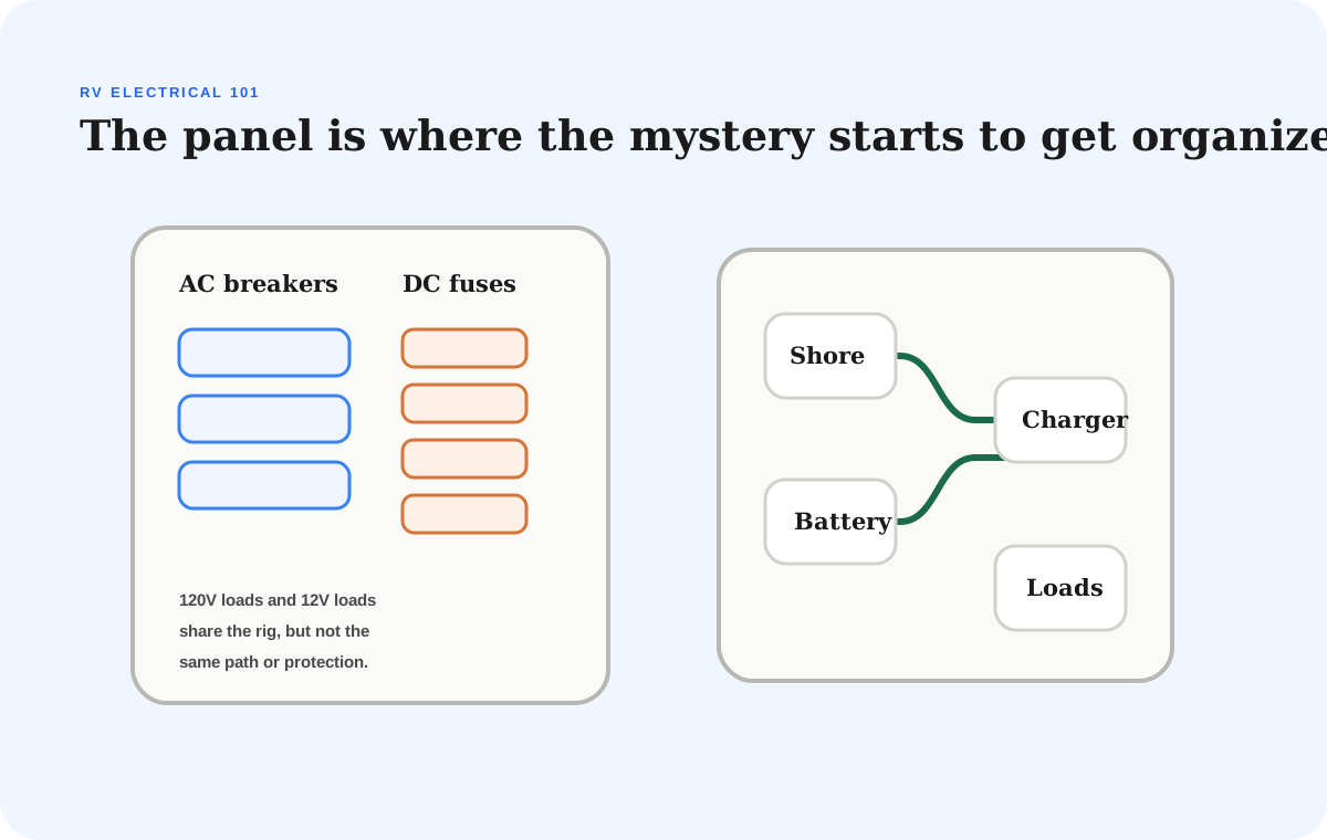
Separate DC and AC loads
Lights, fans, and pumps live on the DC side. Outlets and household appliances live on the AC side.
Step 5
Mark protection points
Fuses, breakers, disconnects, and transfer behavior are where a simple sketch becomes a safe plan.
Step 6
Verify before buying
The actual rig layout, manuals, wire distance, and battery limits decide the final parts list.
Start with power flow, not parts
Most RV electrical confusion starts because the system gets explained as a pile of parts: panel, controller, converter, inverter, battery, fuse, breaker, shore cord, transfer switch, alternator, and outlets.
That is technically accurate, but it is not the easiest way to learn.
A better first pass is to follow the flow of power.
Power enters the RV from a source. A charging device makes that power useful for the battery bank. The battery bank stores energy. The DC distribution panel feeds the core coach systems. An inverter can turn battery power into 120V AC power when you are not plugged in. The AC panel feeds household-style loads when shore, generator, or inverter power is available.
Once that order makes sense, the individual parts become much less mysterious.
The five zones in a simple RV electrical diagram
Compare
RV electrical system zones and what each one does
Use one comparison matrix to scan the practical differences. Small screens stack each row; wider screens keep the first column pinned.
| Spec | Plain-English job | Where it usually connects | What to verify |
|---|---|---|---|
| Power sources | Create or supply energy | Shore cord, generator, solar panels, alternator path | Which sources are AC, which are DC, and which can run at the same time |
| Charging equipment | Turns source power into controlled battery charging | Converter or charger, solar controller, DC-DC charger | Battery chemistry settings, current limits, heat, and cable distance |
| Battery bank | Stores usable reserve for the coach | Battery compartment, shunt, main fuse, disconnect, bus bars | Usable capacity, max discharge current, charge limits, and ventilation or temperature needs |
| DC distribution | Feeds 12V coach loads | Fuse panel, lights, fans, pump, furnace controls, refrigerator controls | Fuse labeling, wire condition, parasitic draws, and voltage drop under load |
| AC distribution | Feeds household-style 120V loads | Breaker panel, outlets, microwave, air conditioner, converter input | Transfer behavior, GFCI protection, inverter pass-through, and load limits |
The 12V side keeps the RV alive
The 12V DC side is the practical heart of most RVs.
It usually powers lights, vent fans, the water pump, furnace controls, refrigerator control boards, USB charging, tank monitors, slide controls, leveling controls, propane detector circuits, and other coach basics.
That is why the battery bank matters even if you do not plan to run big AC loads off-grid. A weak or undersized battery bank can make the whole RV feel unreliable because the core coach systems depend on it.
When you look at a diagram, treat the 12V side as the baseline system. If the DC side is healthy, fused correctly, labeled, monitored, and easy to disconnect, the rest of the upgrade path gets calmer.
If that DC side keeps pulling power after the rig appears off, use the RV parasitic draw guide to measure the standby current before assuming the battery bank is weak.
The 120V side is for household-style loads
The 120V AC side is where RVers often get into trouble because the loads are familiar but the power source is limited.
Wall outlets, microwaves, some kitchen appliances, air conditioners, space heaters, and residential-style gear can demand far more power than the battery bank or inverter can comfortably support.
AC power can come from shore power, a generator, or an inverter. Those sources are not interchangeable in practical terms. A campground pedestal may support heavy loads. A generator may support some heavy loads, but with fuel, noise, and maintenance tradeoffs. An inverter can support selected AC loads only if the battery bank, cables, fusing, and inverter rating are sized for the job.
That is why a diagram should show the inverter as a bridge, not magic. The inverter does not create energy. It only converts stored battery energy into AC power, with losses and current limits along the way.
A diagram is not a final wiring plan
Use a generic diagram to understand the system shape, not to pick final wire gauge, fuse size, breaker size, grounding, transfer switching, or battery protection. Those details depend on the actual components, cable lengths, installation environment, and applicable standards.
How the charging sources differ
Solar, shore power, generator power, and alternator charging all help the battery bank, but they reach it through different equipment.
Solar panels feed a solar charge controller. The controller regulates panel voltage and current into a charging profile the battery can accept.
Shore power usually feeds the RV's converter or charger. That charger supports the DC system and replenishes the battery bank while the RV is plugged in.
If you need the campground-pedestal side of that path, read the RV shore power guide before you compare adapters or protection devices.
A generator often acts like portable shore power. It feeds the AC side, which can then feed the converter or charger.
The alternator path usually needs a DC-to-DC charger on modern lithium upgrades. That charger limits current, protects the alternator, and gives the house bank an appropriate charging profile.
The important idea is this: every source needs the right translator before it charges the battery bank.
If a source is supposed to be charging but the bank is not recovering, use the RV battery not charging troubleshooting guide to trace the source, charger, battery-side fuse path, disconnects, monitor readings, and BMS limits in order.
Where the common mistakes happen
Most beginner electrical mistakes happen at the connection points.
The first connection point is from source to charger. This is where people mismatch a solar array to a controller, assume an old converter is lithium-ready, or pull too much current from an alternator path.
The second connection point is from charger to battery. This is where cable distance, voltage drop, current limit, temperature behavior, and fuse placement matter.
The third connection point is from battery to inverter. This is where a large inverter can overwhelm a small bank, weak cables, missing overcurrent protection, or an underrated disconnect.
The fourth connection point is from inverter to AC loads. This is where transfer behavior, pass-through limits, GFCI behavior, and load shedding need to be clear.
If you are drawing your own system, circle those connection points first. They are where the expensive mistakes tend to hide.
A practical way to sketch your own RV
Start with a blank page and draw six boxes:
- Sources
- Charging equipment
- Battery bank
- DC distribution
- Inverter or inverter charger
- AC distribution
Then fill in what your RV actually has. Do not fill in what you hope to add someday yet.
Write the model number next to every major component you can identify. Add the battery chemistry, battery capacity, inverter rating, solar controller rating, converter model, and whether the shore/generator path uses a transfer switch.
Next, mark what you do not know. Unknowns are useful. They tell you where to inspect before buying parts.
Finally, draw the future upgrades in a different color. That simple separation keeps the existing system and the wish-list system from blending into one confusing plan.
Draw the current system before the dream system
A clean upgrade usually starts with an honest map of what is already installed. If you skip that step, it is easy to buy a part that technically works but creates routing, charging, or service problems inside the actual rig.
What to check before installing anything
Before you drill, crimp, mount, or order the big parts, confirm:
- battery chemistry and charging requirements
- existing converter or charger model
- available battery-compartment space
- safe cable routes between battery, inverter, controller, and panels
- fuse or breaker locations near power sources and batteries
- inverter load plan and expected AC circuits
- shore/generator transfer behavior
- roof layout, shade risk, and combiner location
- alternator charging path and current limit
- whether the work should be reviewed or performed by a qualified RV electrical professional
This checklist is not meant to slow the project down. It is meant to prevent the kind of rework that makes an electrical upgrade feel twice as expensive as it needed to be.
How this guide connects to the calculators
Use the diagram to understand the system shape. Then use the calculators to size the pieces.
The solar calculator helps estimate panel wattage, battery capacity, and inverter targets from daily loads.
The battery calculator helps translate appliance use into usable amp-hours and bank size.
The RV solar installation guide is the next step when you are ready to think about roof layout, controller placement, cable routes, and commissioning.
The RV electrical system 101 guide is the simpler primer if you want the concept pass before the diagram pass.
Final thought
The most useful RV electrical diagram is not the fanciest one. It is the one that helps you explain your own system out loud.
If you can point to each source, identify the charger it uses, follow power into the battery bank, separate DC loads from AC loads, and explain what the inverter is actually doing, you are already ahead of most expensive beginner mistakes.
Frequently asked
Questions RVers usually ask next.
What is the difference between an RV electrical diagram and a wiring diagram?
An electrical system diagram explains how the major parts relate to each other. A wiring diagram is more specific and should include actual wire runs, conductor size, fuse or breaker sizing, grounding, transfer behavior, and component terminals.
Does RV solar power the outlets directly?
Usually no. Solar panels charge the battery bank through a solar controller. Outlets are powered by shore power, generator power, or an inverter that converts battery power into 120V AC.
Can I add a large inverter to any RV battery bank?
Not safely or usefully without checking the bank, cables, fusing, disconnects, and expected loads. A large inverter can pull very high DC current, so the battery bank and protection hardware need to be sized as a system.
What should I identify first in my RV electrical system?
Start with the battery bank, converter or charger model, existing fuse panel, shore power path, inverter if installed, and any solar or alternator charging equipment. Those parts tell you what the system can already do and what needs verification.
Freshness note
Last checked April 10, 2026
This topic can change when products, plans, prices, campsite rules, or fit guidance move. These notes show what was reviewed most recently.
This review included
- Checked that the diagram explains power flow without pretending to replace component manuals, code requirements, or qualified electrical review.
- Reviewed the guide against the solar, battery, inverter, and DC-to-DC charger clusters so the handoffs are consistent.
- Added clear safety boundaries around wire gauge, fuse sizing, transfer switching, grounding, and battery protection.
Recent change log
April 10, 2026
Published a diagram-first RV electrical guide for readers who need to see the whole system before buying parts.
April 10, 2026
Added a visual power-flow map, component-role table, safety boundary checklist, and system-reading workflow.
Broader editorial corrections are tracked on the Corrections and Updates page.